![]()
Library, electrical template type
Library, electrical location format
For automatic dividing of typicals you can define rules in location formats. These location formats are available for Electrical, Documents Logical and Scada. This page explains how you can organize your typicals, templates and template types on the basis of Electrical.
Location formats can be specific for a customer or for a project. Examples of rules can be:
Main circuit diagram starting from page number 100
Control circuit diagram starting from page number 300
PLC Rack overview starting from page number 600
Other rules can relate to the drawing structure, for example Eplan uses:
Level 1 (== Level)
Level 2 (= Level)
Level 3 (++ Level)
Level 4 (+ Level)
For some projects all levels are used, for other projects for example only level 2 and level 4. The usage of these levels can be different as well. For example some drawings are structured functionally, others might be structured according to panels or locations.
Example functional structure:
Level 1 (Eplan ==), S88 level Site
Level 2 (Eplan =), S88 level Area
Level 3 (Eplan, ++), S88 Process cell
Level 4 (Eplan, +), Unit
Example panel wise structure:
Level 2 (Eplan =), Main panel (MCC)
Level 4 (Eplan +), Junction box (JB)
Other rules can be related to the page type used. (Template). For example for Main Circuit Diagrams a template might be used with the 3 Power phases in the top of the drawing L1, L2, L3. When an electrical engineer designs an electrical drawing he implements all these rules to assemble the electrical drawing.
Typical Manager® allows the user to create and store this set of rules in the library. Furthermore this set of rules can be applied to a project. This allows the Typical Manager® software to create the electrical drawings based on this set of rules and the typicals supplied by the process tags.
To allow for this automatic creation of drawings certain values must be set. For example the width and height of a template must be known. If a typical fits on the template it is placed on the template, otherwise a new template is used to create a new page. Below all the steps for defining the assembly rules are stated.
A set of electrical template types must be defined. These template types
are used to group related typicals and templates. Examples of electrical
template types can be:
- Main circuit diagram
- Control circuit diagram
- PLC rack overview
- Emergency stop circuits
- Single line
See also:
Electrical templates are used as a background, to place the typicals
on. Examples of templates are:
- Main circuit power lines 3 Phases + Neutral and Earth
- Main circuit power lines 3 Phases and Earth
- Main circuit power line 1 Phase + Neutral
To enable the automatic placing of typicals the width and height of the template must be known. The width and height must be entered manually.
See also:
For each typical added to an electrical module, settings have to be made. The template type for a typical must be selected. For an example, the main power of a direct online motor belongs to electrical template type "Main circuit diagram". It is also possible to place a typical onto a new template. To do this the "New template" check box must be checked.

See also:
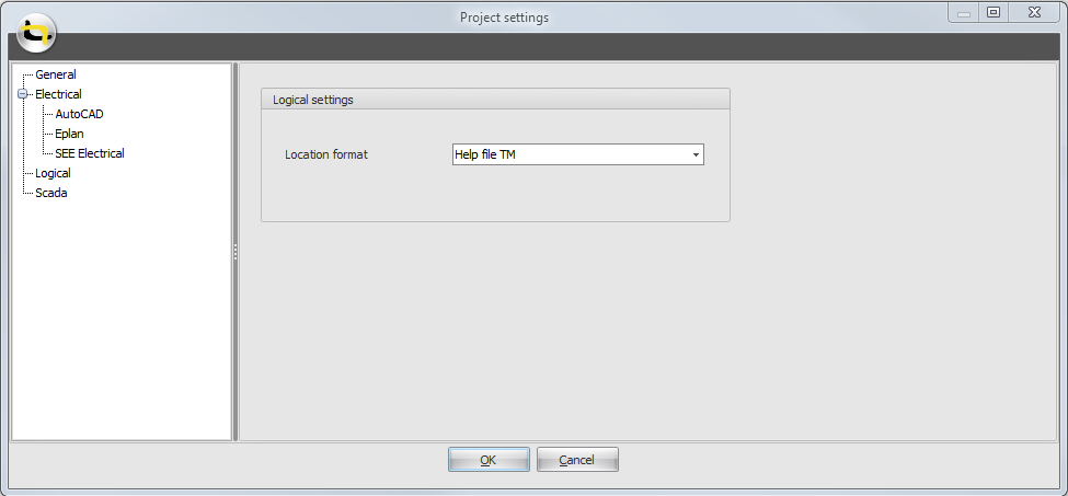
A set of rules can be defined in the library in a location format. Several
formats can be defined. In the project settings one of these location
formats can be selected/activated.
See also:
For each project an electrical/logical/scada location format can be
selected.
See also:
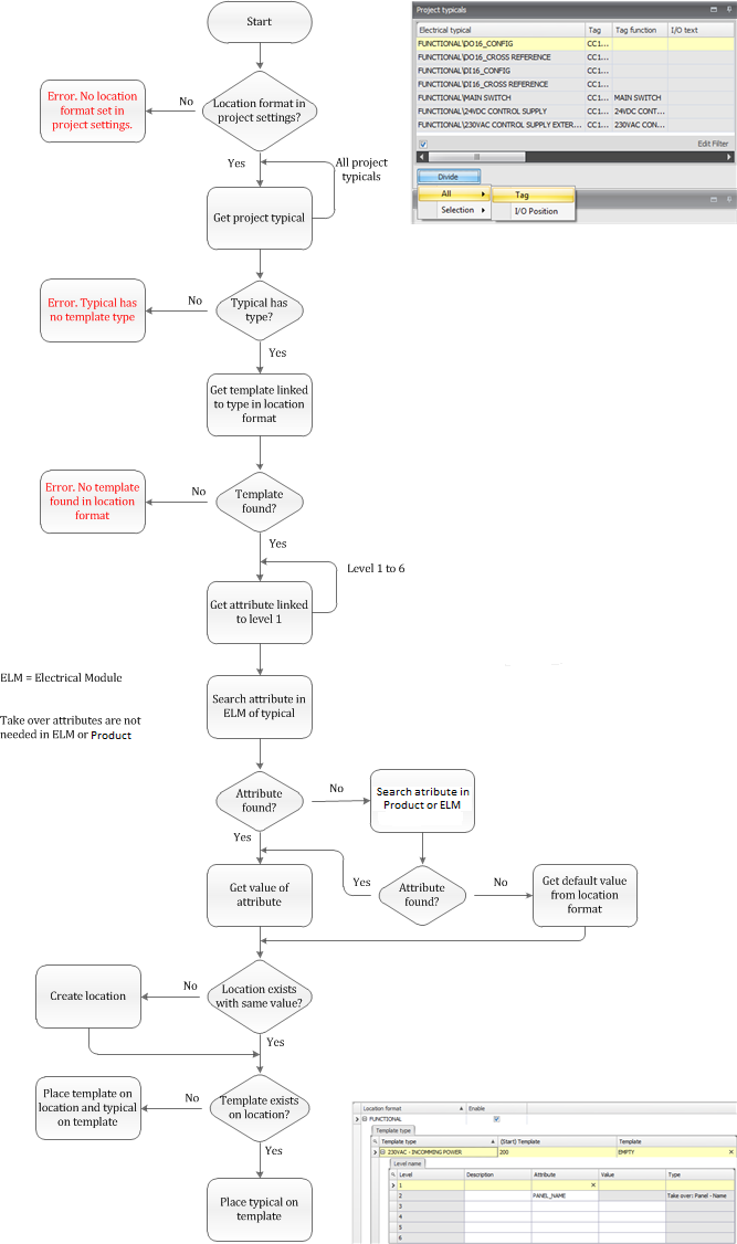
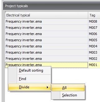
In the electrical location screen it is possible to automatically divide all typicals or divide a selection of typicals. By using this command, the electrical location tree is automatically created according to the rules made in the selected location format for this project. The typicals are placed on the appropriate location and template.
See also:
It is possible to use attributes on levels. You can fill in a default value. If you automatically divide your project typicals, Typical Manager® will use this default value as the name of the level. But if you attach this attribute to the electrical module, which contains the electrical typicals you want to divide, Typical Manager will use the value of this attribute as the name of the level. If the attribute is empty, the level won’t be created. You also can attach this attribute to the product, which contains the electrical typicals you want to divide. In this case, Typical Manager will use the value of this attribute as the name of the level. If the attribute is empty, the level won’t be created.
So, first Typical Manager® will look in the electrical module. If the attribute isn’t found then Typical Manager® will look in the parent product Attribute sill not found, Typical Manager will look to the default value in the location format.
Example
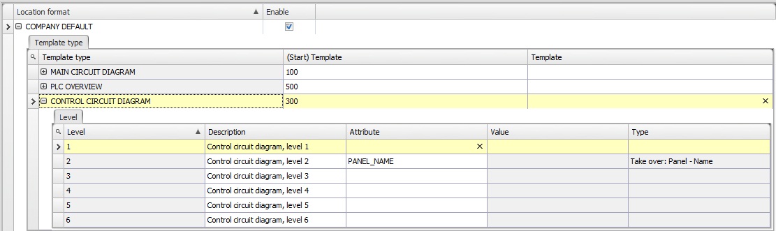
We have the following electrical location format.
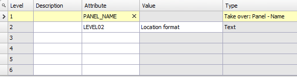
If we now divide our typicals in a project, a level 1 will be created with the name of the panel of the typicals and a level 2 will be created with the name ‘Location format’:
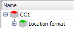
As you can see, a level 1 called 'CC1' is created because all typicals are placed on the same electrical panel. Level 2 is called 'Location format', because Typical Manager® gets this value from the location format.
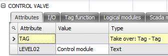
Now we add attribute ‘LEVEL02’ to the product which contains the electrical modules, which contains the electrical typicals. As value we give in ‘Control module’:
Notes:
1. If you add an attribute to a product, and the product is already attached to a function in a project, the attribute will be added to the function in your project. But, the default value you fill in here won’t be copied to the project. Therefore you need to relink the product to the function. Otherwise you can fill in a project specific value for this attribute in the Project structure, or Engineering window.
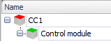
If we now divide our typicals, a level 1 will be created with the name of the panel of the typicals and a level 2 will be created with the name ‘Control module’:
If you leave attribute ‘LEVEL02’ blank in the product, Typical Manager® won’t create a level 2. Then you only get a level 1, so the default value in your location format is not used.
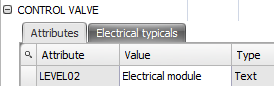
You also can attach attribute ‘LEVEL02’ to the electrical module, which contains the electrical typicals you want to divide. As value we give in ‘Electrical module’.
Remember to relink the electrical module to the product and the product to the Function if you already use this electrical module in a project and you want to use this default value in your project. Otherwise you can fill in a project specific value for this attribute in the Project Structure, or Engineering window.
If we now divide our typicals, a level 1 will be created with the name of the panel of the typicals and a level 2 will be created with the name ‘Electrical module’:
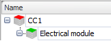
As said before, if you leave attribute ‘LEVEL02’ blank in the electrical module, Typical Manager won’t create a level 2. Then you only get a level 1.
See also: